Microsampling Apparatus
Microsampling may be done with either Microdrilling or Micromilling techniques.
The basic difference between these two modes of operation, Microdrilling and Micromilling, is the following.
- In Microdrilling, the sample is stationary and the drill cutter is moved around the sample on the desired areas, usually using video overlays of CL and TrL to sample the desired areas.
- The Micromill has a rigidly positioned milling cutter and the sample is moved on a computer-controlled X,Y stage to move the desired areas against the milling cutter. The areas may be preselected or the operator may use a type of joy-stick to control the sample position.
In both cases, a vacuum-operated Micropipette is used to collect the material.
Microdrilling System
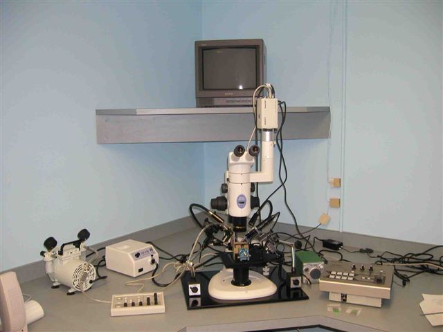
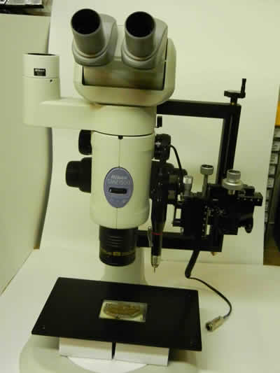
Microsampling apparatus described by Fouke and Rakovan (2001). This apparatus combines CL and transmitted light images to precisely locate sampling locations. The sample is mounted on a stereo microscope that is fitted with a microdrill, a vacuum pipette to collect the drilling dust, and illuminators. The location of the desired site is accomplished with the superposition of the image from the stereo microscope onto the CL image obtained separately. University of Western Ontario.
Microsampling can be achieved using microdrilling or micromilling techniques. For more information about these techniques, look here.
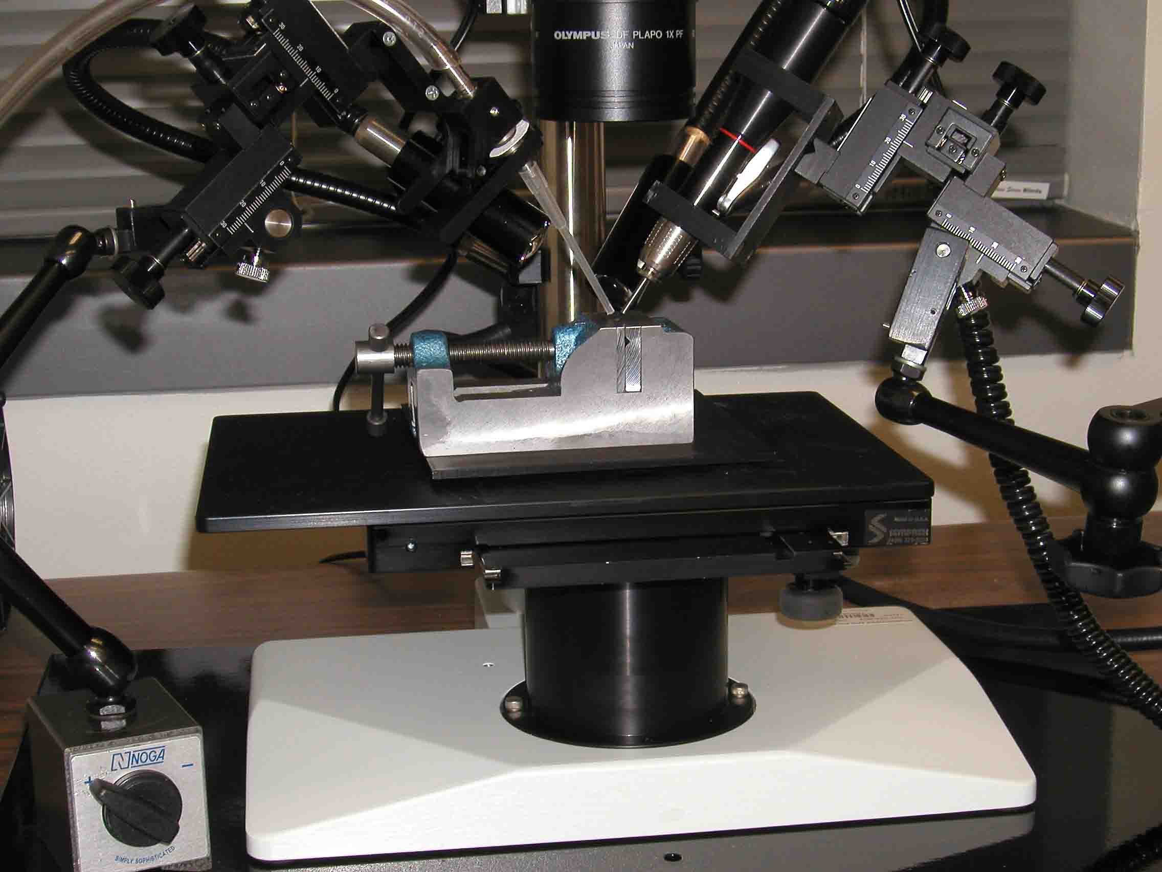
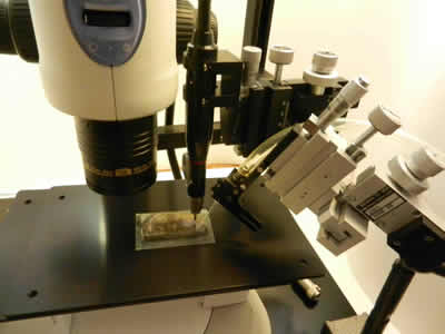
Microsampling apparatus in action, Texas A & M University. Closeup of the microdrill and micropipette on the stereo microscope. The sample is held in a small vise.
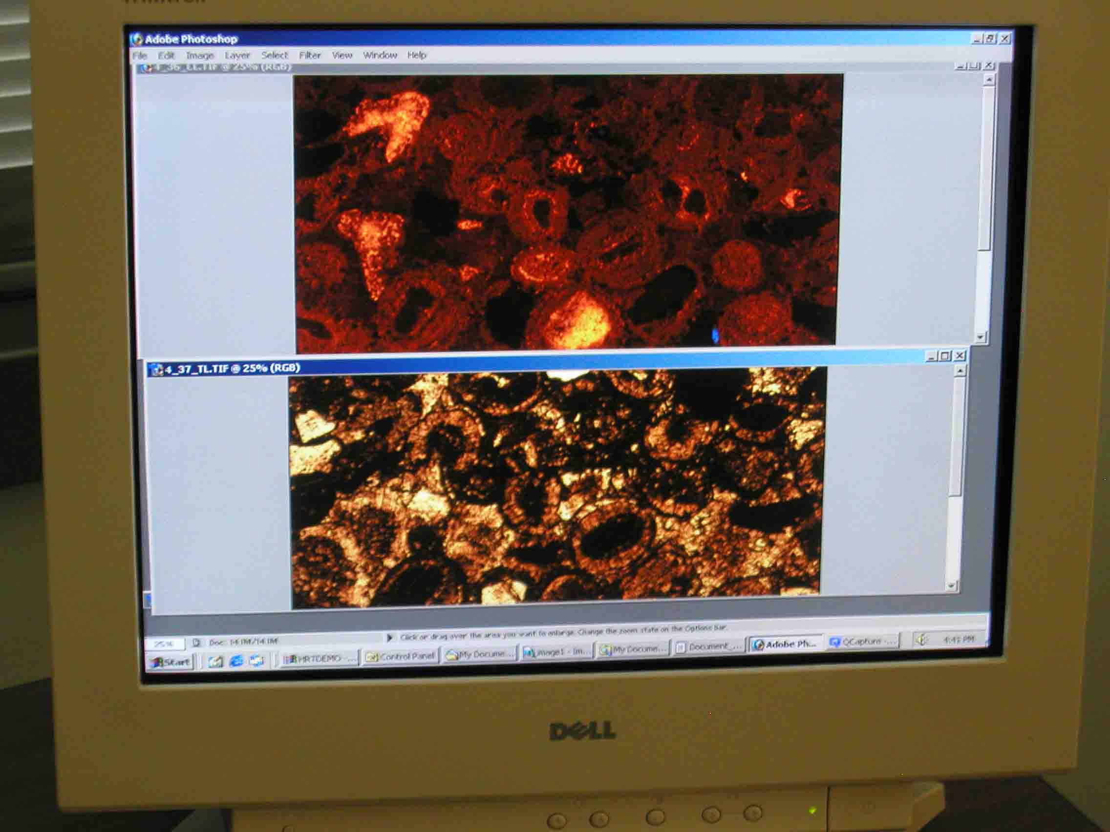
Example of mixing of TrL and CL images on video screen during microdrilling. From this, the images are superimposed exactly and expanded to full screen to allow location of microdrill. Texas A & M University.
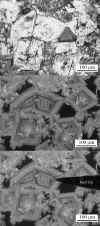
View of superposed black and white image from stereo microscope drilling station and CL image. The drill burr, which may be as small as 12 microns in diameter, is shown in the overlay and by easy manipulation can be located at the precise spot of interest on the sample.
Microdrilling Procedure for Thin Sections and Slabs
- Sample is studied with CL and area of interest is photographed.
- Sample is transferred to stage of microdrilling apparatus stereo microscope.
- Sample is inspected with TrL or reflected light on stereo microscope and video image is sent to first channel on video mixer.
- Stored CL image is converted to video and sent to second channel on video mixer.
- The two video images are overlapped and area of interest located.
- Microdrill and pipette are brought to area of interest and drilling is done.
- Depending on drill size and sample quantity required, multiple drill holes may be needed — please see nomogram.
- Filter paper containing collected sample is removed for analysis.
Micromilling System
The micromilling system consist of a rigid mount for the microdrill hand-piece which is held in a vertical position, closely adjacent to the microscope itself. The hand-piece can be raised and lowered with a coarse adjustment screw and the final adjustment can be made with the precision X,Y,Z micromanipulator that the drill hand-piece is attached to.
The standard microscope stage is replaced by a stage driven by computer-controlled motors in the X and Y directions.
Another view of the micromill including the micropipette for sample collection.
The drill hand piece can be removed from the Micromill assembly, if desired, and used on a flexible arm/magnetic clamp as a normal Microdrill.
